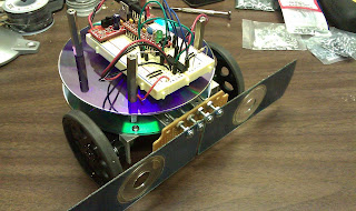
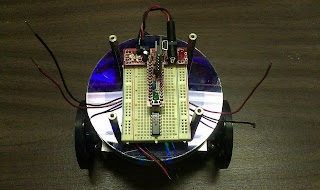
Now that I have the physical form of the robot, I guess it is time to work on the controller and get something going. Initially, this was a bit more difficult than I first thought.
I encountered a bit of confusion over the difference between the pin numbers on the controller chip (Ardweeny with an ATmega328) and the "pins" in the Arduino development environment. My brother, Steve, later explained to me that this is because the Arduino environment pins are the pins on the Arduino board as opposed to the pins on the actual microcontroller chip. At any rate, I eventually figured it out with the help of the small pin lables on the Ardweeny circuit board and some online research.
Once I had the pins straight, my control circuit using the TI L293D worked very well. I simply tied the EN1,2 and EN3,4 pins to +5v through a current-limiting resistor, tied the A pins to the Ardweeny, and tied the Y pins to the servos.
I interfaced the bumper switches through current-limiting resistors and draw-down resistors so that when the switches were closed they would trigger a HIGH state on the input pins.
By the way, after playing with the robot for a while, modifying the code, and coming up with a reasonable navigation routine, I decided to call the robot "Twitch." Here is the schematic:
Twitch Robot Schematic.
The code is fairly simple. One aspect that might not seem straight-forward to some is that I used Pulse Width Modulation (PWM) to calibrate the servos while the bot was moving forward and backward. I am not sure why, but the bot moves in an arc if supplying full voltage to the servos by triggering the Ardweeny pins digitally (HIGH/LOW). To compensate for this, I use PWM (or Analog output as it is called in the Arduino) on the servos to gain a finer control over how much they rotate during any given time period. With PWM, you can make a servo move at an 8-bit resolution (256 values) of speed instead of simply off or on.
Here is a link to the code:
Twitch Controller Sketch
Here is the code text:
/*
Twitch3
Twitch Robot Control
2010 by Karl Demuth - use as you like!
This control program allows Twitch to navigate by checking input from left and
right bumpers and turning accordingly. The servo control is done with two modified
servos (left and right) driven by a Texas Insruments L293D h-driver.
*/
int pin_LED = 13; // LED connected to digital pin 13
int pin_RightServo_1A = 5; // Right Servo pin output to 1A on L293D
int pin_RightServo_2A = 6; // Right Servo pin output to 2A on L293D
int pin_LeftServo_3A = 9; // Left Servo pin output to 3A on L293D
int pin_LeftServo_4A = 10; // Left Servo pin output to 4A on L293D
int pin_LeftBumper = 12; // Left Bumper Switch
int pin_RightBumper = 1; // Right Bumper Switch
int state_LeftBumper = 0; // Intermediate holder of left bumper state
int state_RightBumper = 0; // Intermediate holder of right bumper state
int calibration_LeftServo = 255; // calibration of PWM output so that when going
// forward or backward, the robot goes straight
int calibration_RightServo = 190; // 0 = no output, 255 = full output
// setup() runs one time when the sketch begins and initializes pins and variables
void setup() {
// initialize the digital pin as an output:
pinMode(pin_LED, OUTPUT);
pinMode(pin_RightServo_1A, OUTPUT);
pinMode(pin_RightServo_2A, OUTPUT);
pinMode(pin_LeftServo_3A, OUTPUT);
pinMode(pin_LeftServo_4A, OUTPUT);
pinMode(pin_LeftBumper, INPUT);
pinMode(pin_RightBumper, INPUT);
}
// the loop() method runs over and over again,
// as long as the Arduino has power
void loop()
{
state_LeftBumper = digitalRead(pin_LeftBumper);
state_RightBumper = digitalRead(pin_RightBumper);
if ((state_LeftBumper == HIGH) && (state_RightBumper == HIGH)) {
// both bumpers are triggered meaning that Twitch hit something headon
digitalWrite(pin_LED, HIGH);
reverse();
}
else if ((state_RightBumper == HIGH) && (state_LeftBumper == LOW)) {
// hit something on the right, so we'll turn left a bit (avoid_right)
digitalWrite(pin_LED, HIGH);
avoid_right();
}
else if ((state_LeftBumper == HIGH) && (state_RightBumper == LOW)) {
// hit something on the left, so we'll turn right a bit (avoid_left)
digitalWrite(pin_LED, HIGH);
avoid_left();
}
else {
// we're not hitting anything, so let's proceed forward
digitalWrite(pin_LED, LOW);
forward();
}
}
// forward() - activate both servos to go forward
// - uses the calibration values set toward the top of this program so Twitch
// actually goes somewhat?? straight
void forward()
{
analogWrite(pin_RightServo_1A, calibration_RightServo);
digitalWrite(pin_RightServo_2A, LOW);
analogWrite(pin_LeftServo_3A, calibration_LeftServo);
digitalWrite(pin_LeftServo_4A, LOW);
}
// backward() - activate both servos to go backward
// - uses the calibration values set toward the top of this program so Twitch
// actually goes somewhat?? straight
void backward()
{
digitalWrite(pin_RightServo_1A, LOW);
analogWrite(pin_RightServo_2A, calibration_RightServo);
digitalWrite(pin_LeftServo_3A, LOW);
analogWrite(pin_LeftServo_4A, calibration_LeftServo);
}
// rotate_right()
// - activates the left servo forward and the right servo backward to rotate
// Twitch right
void rotate_right()
{
digitalWrite(pin_RightServo_1A, LOW);
digitalWrite(pin_RightServo_2A, HIGH);
digitalWrite(pin_LeftServo_3A, HIGH);
digitalWrite(pin_LeftServo_4A, LOW);
}
// rotate_left()
// - activates the right servo forward and the left servo backward to rotate
// Twitch left
void rotate_left()
{
digitalWrite(pin_RightServo_1A, HIGH);
digitalWrite(pin_RightServo_2A, LOW);
digitalWrite(pin_LeftServo_3A, LOW);
digitalWrite(pin_LeftServo_4A, HIGH);
}
// avoid_right() - turn left a bit
// - activates only the right servo to turn left a bit
// - left turning is done by turing left wheel backward
void avoid_right()
{
digitalWrite(pin_RightServo_1A, LOW);
digitalWrite(pin_RightServo_2A, LOW);
digitalWrite(pin_LeftServo_3A, LOW);
digitalWrite(pin_LeftServo_4A, HIGH);
}
// avoid_left() - turn right a bit
// - activates only the left servo to turn right a bit
// - right turn is done by turning right wheel backward
void avoid_left() // by turning right
{
digitalWrite(pin_RightServo_1A, LOW);
digitalWrite(pin_RightServo_2A, HIGH);
digitalWrite(pin_LeftServo_3A, LOW);
digitalWrite(pin_LeftServo_4A, LOW);
}
// reverse()
// - this routine reverses Twitch by backing up a bit, then
// rotating right a bit
// - this routine is used when Twitch hits something headon
// so that the robot reverses direction
void reverse()
{
backward();
delay(1500);
rotate_right();
delay(1500);
}


