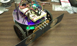
Ok, time for some brutal honesty... this is going to be a bare-bones bot, just to get through this. Yeah, I have a TON of ideas which I cannot wait to implement, but time is moving along and the deadline draws near. What made me think that family life and a bot-building contest were compatible is beyond me!!
So, I thought the chassis was the hump. GEEZ!... I hadn't even really given much thought to how I would mount my sensors (bumper switches in my case)! So, I had a look at the micro-switches that came in the Jameco pack. They both have two small mounting holes. Great! No problem!... except I couldn't find anything in my parts bins small enough to fit through the holes. My brother, Steve, who is also an entrant in this contest and obviously way brighter than me, read the spec sheet for the switches and found that they require a 2M screw (two millimeter metric). After searching the typical local DIY stores, I came up empty. Time to reconsider my mounting plan.
My next thought was that I could mount the switches to some perfboard by soldering the switches directly to the board. This ended up being the way I fabricated the final bumper assembly. I soldered the switches to the perfboard and then mounted some bumpers cut from CDs in such a manner that the bumpers would bend and activate the switches. My final assembly accounts not only for side strikes, but for headon strikes as well. Later on, after testing the robot, it was obvious there were some weaknesses in this design. First, the bot can get hung up under overhangs. Second, sometimes when the bot tries to back a bit to avoid an obstacle, the bumpers can get caught on something, actually prying the bumper away from the switch. Not ideal, but it will work for a first pass.
First, I got the parts together and cut some more angle brackets to mount the bumper assembly to the bot. Then I checked placement of the switches.
Then I cut the CDs and mounted one to the assembly to see how it worked. It worked, but it really needed some more leverage.
Seeing that the bumpers needed a bit more leverage, I drilled two holes a little closer to the center of the perfboard, cut the CDs flush in the center, and ended up getting much better results. By the way, those are 4-40 x 1" screws. Oh, and please ignore how my home made angle brackets aren't square!!
After making sure the bumpers would activate the switches, I wanted to mount a current-limiting resistor to the assembly. I am not real sure now why I did not do this on the protoboard, but at the time it seemed like a good idea. Yeah, it was kind of painful. I hate perfboard, as you can see by my horrible-looking solder job!
Here are some pictures of the test-fit on the bot. I later re-cut different bumpers to get them a bit more even and re-drill the holes so that they were mounted a bit more square.
Monday, May 10, 2010
Subscribe to:
Post Comments (Atom)


No comments:
Post a Comment