Things are moving along for me on my robot build for the Make: Robot Build Contest. I'm having a blast!
So, my next step is to modify a servo for continuous rotation. Most servos are designed to allow only a limited degree of freedom in rotation and the Hitech HS-322HD that comes in the Jameco build kit is no different. Since we're going to mount wheels to each servo, we'd really like for them to be able to turn (and keep turning) 360 degrees in either direction.
I'm going to use a couple special tools. The first is a desoldering vacuum, or "solder sucker" as some might call it. This will help remove solder when I desolder the servo's controller board from the motor. The second tool is a micro cutter. This is basically a small pair of snips.
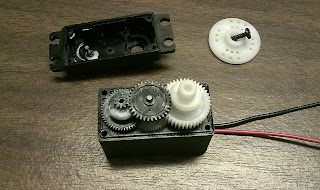
Here is our unmodified servo, a Hitech HS-322HD.
First, we're going to remove the four screws from the bottom of the servo and lift off the bottom cover.
Next, we'll desolder the motor from the controller board. We do this primarily so that we can remove the potentiometer in a later step without damaging it. To desolder the motor, heat the two solder lugs on the motor (the two big solder joints at the opposite end of the servo from where the control wires enter), one at a time, and use the desoldering vacuum to pull the solder from the lugs. Once all the solder is removed, use a small, flat screwdriver to lift the controller board away from the motor.
One you have the controller board free from the motor, you will see three wires running from the board to a potentiometer. There is a small screw holding the potentiometer in place. Remove the screw, free the potentiometer, and pull the entire controller unit free from the servo.
So, now we have separated the controller from the servo. In the future we can reinstall it back into the servo for another project, use it separately in another project, or raid it for its parts!
Our next step will be to solder two wires to our motor. You could use the original control wires from the servo, but I chose to just add a couple of my own. I fashioned a small hook in the end of each wire to loop through the lugs of the motor. This will help avoid having the wires easily pulled out of the servo.
Once we have the wires hooked through the lugs, crimp them with a pair of needle-nosed pliers to help hold them in place. Then solder the wires to the motor lugs.
Our motor is all set now, so we need to concentrate on the gears next. There is a small tab on the main drive gear that was originally designed to keep the servo from rotating completely. We need to remove the tab, so remove the top cover of the servo to expose the gears, starting by removing the screw and wheel on top of the servo.
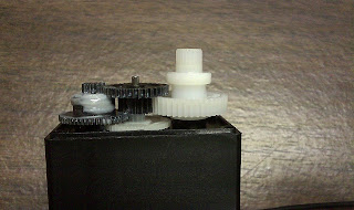
Let's take a profile picture of the gears so that we can remember how they were assembled! Then we'll remove the main gear (large white gear) and separate the bearing sleeve from it.
In the close-up picture, you can see the small tab that we need to remove so that the gear will be able to rotate fully. There are some options regarding how to remove the tab. I opted to use a pair of micro snips to avoid getting sawdust in the grease. However, you could likely use a small dremel cutter to saw it. I also read about someone melting the tab to remove it. The danger in using the snips is that it could cause the gear shaft to split. I read about this possibility in a number of online posts where folks had accidentally split the gear or gear shaft when cutting. To try to minimize this possibility, I decided to make my first cut parallel to the gear shaft and then make my second cut perpendicular to the shaft. To further minimize the risk, I made sever small cuts in this fashion as opposed to trying to remove the tab with only two large cuts.
Once the tab has been removed, it should be nice and flush with the gear so that it does not catch the stop that is built into the case of the servo.
We can now reassemble the gears. Don't forget to place the bearing sleeve back onto the main drive gear.
You can now replace the top and bottom covers of the servo and mount the wheel to the main drive gear instead of the original white horn disk.
Now we can test the servo to make certain it turns continuously in both directions. If you have your voltage regulator built, you can connect the servo wires to the power bus of your breadboard. Once you are sure it turns in one direction, flip the polarity of the wires and try it the other direction. This isn't quite the way the servos will be powered in our final robot, but it is a good test to make sure our modification was successful.
Sunday, April 4, 2010
Friday, April 2, 2010
Ardweeny
Here are some pictures of my Ardweeny build, including some tips along the way.
Solarbotics documents this kit fairly well, so I won't bore you with all the step-by-step details. Here is the completed board prior to attaching it to the ATmega328.
Slide the ATmega328 between the pins of the Ardweeny board, making sure that the board pins are perfectly aligned with the ATmega pins. Do not slide the tips of the board pins any further than the wide tops of the ATmega chip pins.
Solarbotics warns not to let solder run down the pins of the ATmega328 when you solder-tack it to the pins of the Ardweeny board. This is critical so that the pins of the ATmega will fit correctly into your breadboard. You can see here that I flipped the entire unit upside down for soldering to help make sure this didn't happen. Boy, was I glad I did this! If you look closely at the full-sized picture, you'll see that some solder ran down the leftmost pin of the Ardweeny board. This is fine, as that portion will not be inserted into the breadboard, but it would have made for some difficult rework if it had run down the leg of the chip. Another tip that might help is to solder the four corner pins first to help ensure the chip does not shift position during soldering.
Here is a profile shot so that you can see the gap between the top of the ATmega chip and the bottom of the Ardweeny board. This is normal if you assemble them correctly. Oops! I didn't leave enough room on the breadboard for the h-drive chip! I'll have to move the Ardweeny.
Here is the breadboard with the three main components: the voltage regulator, the Ardweeny, and the H-drive chip. Time for refreshments!
Voltage Regulator
Thought I would post some pictures of the voltage regulator. Although it sounds like the build tutorials will skip using the DC jack, I installed it regardless, as I will likely use this nice little kit for other projects in the future. For now, I'll solder a DC plug onto the end of my battery leads, making both more flexible down the road. One note: I could not find in the Solarbotics documentation for the kit what the correct polarity was for the jack. It ends up that the ring is grounded and the pin is powered. Make sure if you use the jack/plug combination that you get your polarity correct, otherwise you will likely damage your 7805 regulator, as I did once in the past on another project.


Subscribe to:
Comments (Atom)


